2024 Crescendo
Triple Quarter Pounder With Bees
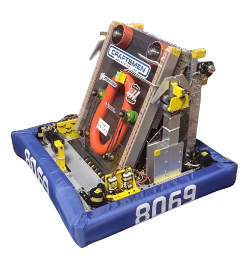
In 10 weeks between early January and late March of 2024, the team built a robot, which was called the Triple Quarter Pounder with Bees, to compete in the St. Louis Regional. The team had 11 students between 14 and 18 years old, each working on mechanical features and/or software for the robot. We placed 8th out of 46 teams in the competition. Due to early alliance selection picks, we moved up to be the 5th seed alliance captain out of the 8 alliances in the playoffs. Alliances are comprised of 3 teams each. This year the team did much better than previous years since we took into account the lessons we had learned previously.
Game Description
For the 2024 game challenge, the robot carries foam rings, known as Notes, into the two scoring areas; the Amp and the Speaker. At the end of the match, the robots climb onto the Stage, made up of three sides, each with a chain for the robots to reach for.
Drivetrain
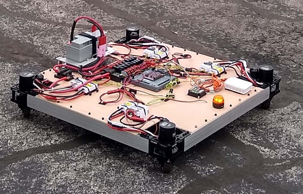
This year, we switched to swerve for our drive train. Previously, we used tank drive, which is a type of drivetrain that has a set of wheels on each side that are linked together. Swerve drive, on the other hand, uses four wheels, one in each corner, that are powered independently. The wheels are also not fixed in a specific direction, instead being able to rotate relative to the robot. This allows the robot to drive in any direction without turning. It is also possible to drive straight while spinning the robot. This makes the robot much more maneuverable, and makes it much easier to line up with game pieces or field elements.
Intake
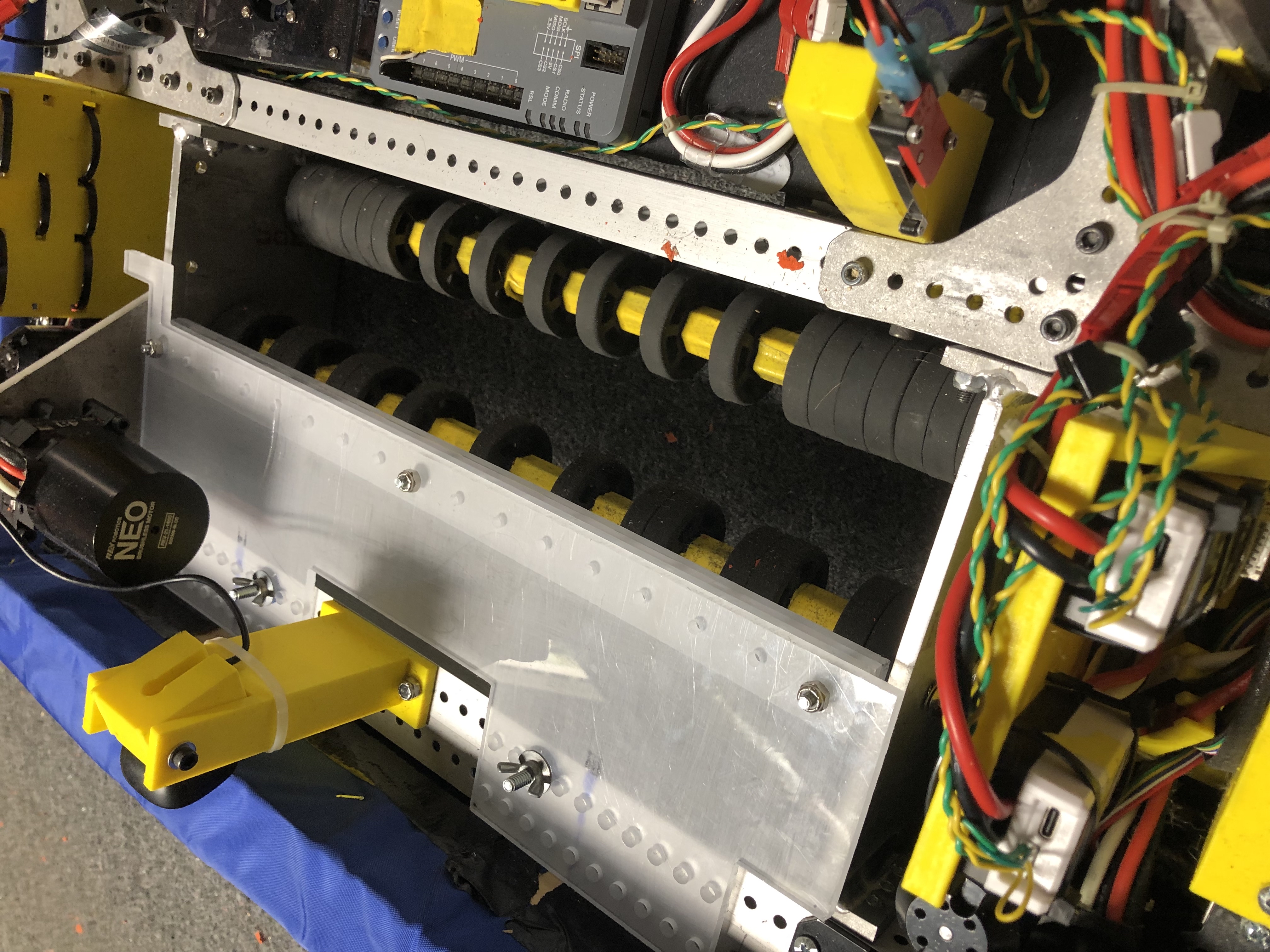
The intake consists of two rollers that spin in opposite directions. We adapted it from a prototype that the Cranberry Alarm Robot In Three Days team published at the beginning of build season. We also designed our bumpers specially to allow us to intake notes beneath it, taking inspiration from team 1706, the Ratchet Rockers. We decided to make them with the front part higher than the rest to prevent notes getting stuck under our robot as we drove over them. We initially had issues with notes traveling through the intake too quickly and jamming, and so we added guards that contain the notes as they pass through the intake to prevent the notes from getting stuck.
Shooter
Indexer
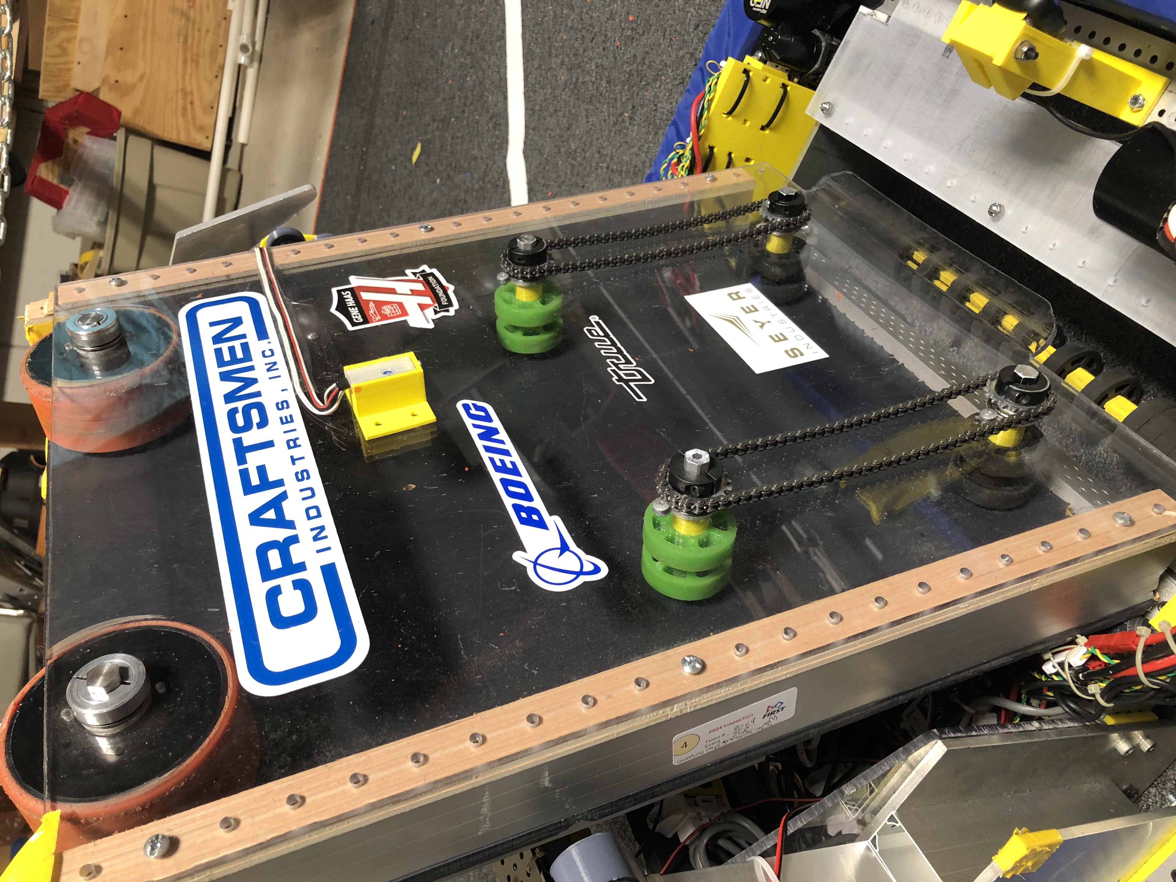
One of our main subsystems this year was our shooter, which was made to launch notes off of an adjustable base. One of our goals was to be able to hold the notes until we were ready to shoot. This was accomplished by the indexer. It uses four rollers that use squishy rubber wheels to hold the note in place on the board so it is always in the same spot. The front two wheels are powered by motors so that we can supply force to deliver it to the shooter flywheels when we are ready to fire. Power is transferred to the back wheels with a chain drive. Our original plan was to use belts with a backing to hold the note in place. One issue we had was proper belt tension. We ended up running out of time to work on the belt idea, so we switched over to the four-wheel system with a sensor that told us when we had the note in the right place.
Shooter Wheels
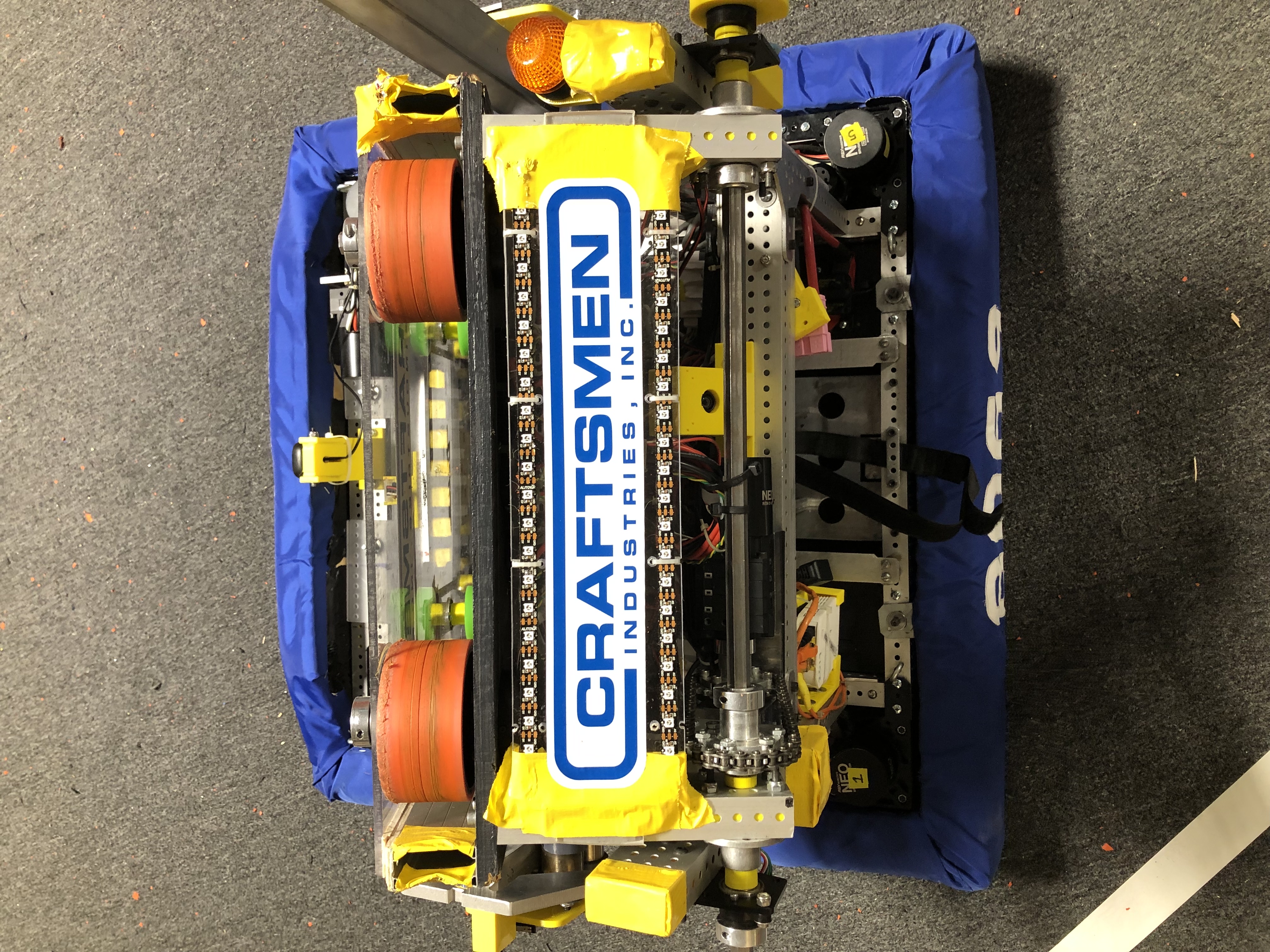
Our shooter system has two independently moving flywheels, each running in opposite directions. These flywheels have two wheels stacked on each axle, giving us ample surface area to grip the note firmly and to give it as reliable a shot as possible. The flywheels run off of two NEO motors, and work in conjunction with the indexer to give it the push it needs to shoot as hard and as far as we need it to. The shooter was designed using a plywood prototype with a slot for one wheel so that we could adjust the compression on the note as needed until we settled on a position that we liked. We then moved the same slot concept to a second board to determine where we wanted the indexer to sit, as the indexer gives us a bit of a boost to send the note on its way. One issue we faced was proper wheel gripping: we needed the wheels to hold the note so that it could throw the note, but not so tight that it shredded the note. The solution we found was to find wheels with a hard plastic interior and a firm but grippy rubber outside.
Angle Adjustment
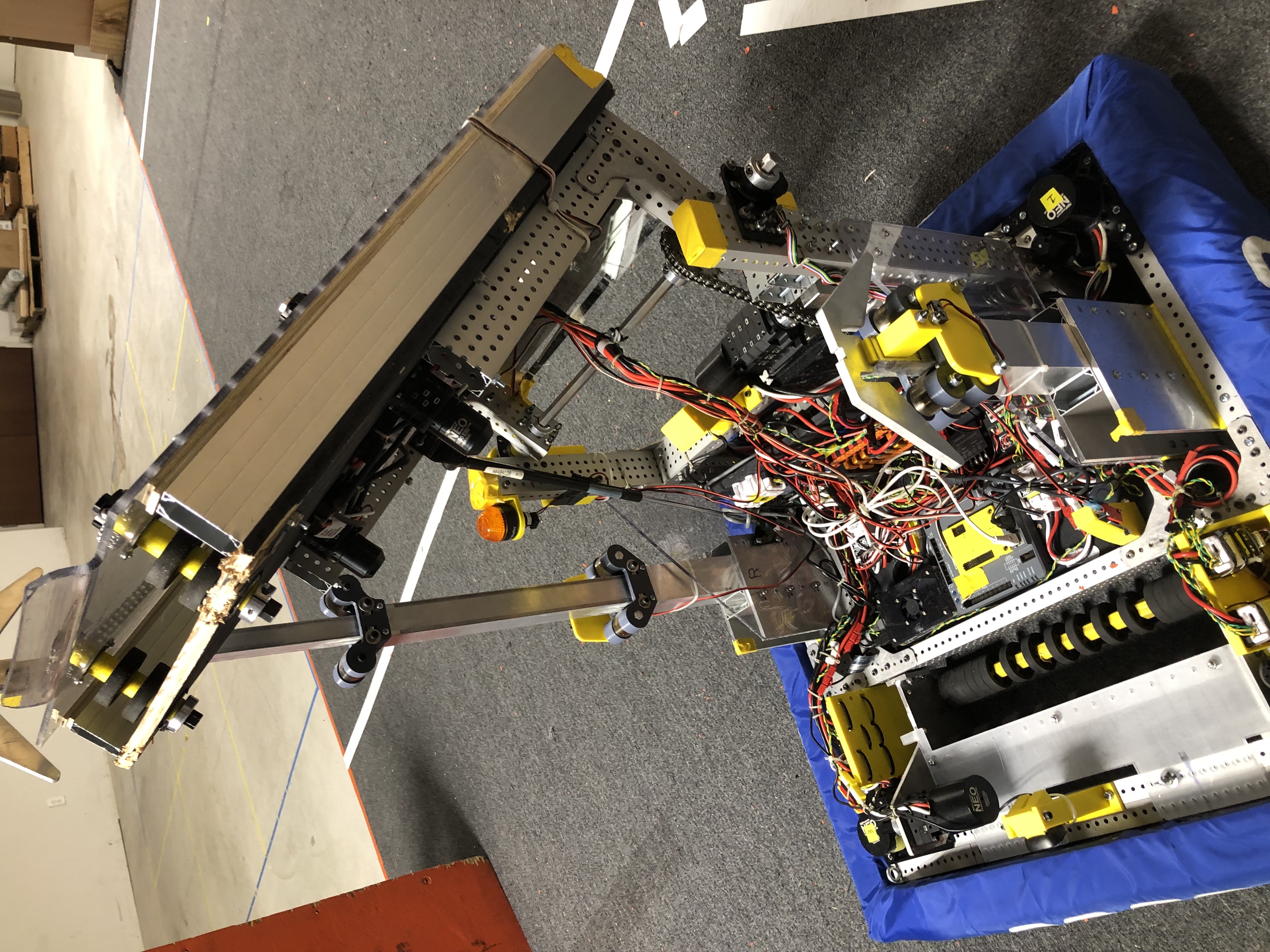
Because we wanted to be able to score from multiple locations, we decided to add a way to adjust the angle of the shooter. We also found by testing in CAD that with the correct geometry, by offsetting the shooter system from the pivot bar, we could adjust our angle enough to shoot down into the Amp while still pivoting down low enough to fit underneath the Stage. While our angle design enabled us to simplify our robot by combining multiple functions into one mechanism, it presented a lot of unexpected issues during manufacturing. We decided to go with a chain drive rather than direct drive because of space constraints, but we ran into issues with the chain skipping. Because the chain was attached in the middle of a long shaft and there were many joints between the two sprockets, there was a lot of flexing. We solved the issue by increasing the sprocket size and chain size, adding support brackets and struts, and mounting the motor to a solid block of steel. We also used a gas spring similar to what holds up a car trunk to lighten the load on the motor and chain system and make the angle more precise to control.
Climbers
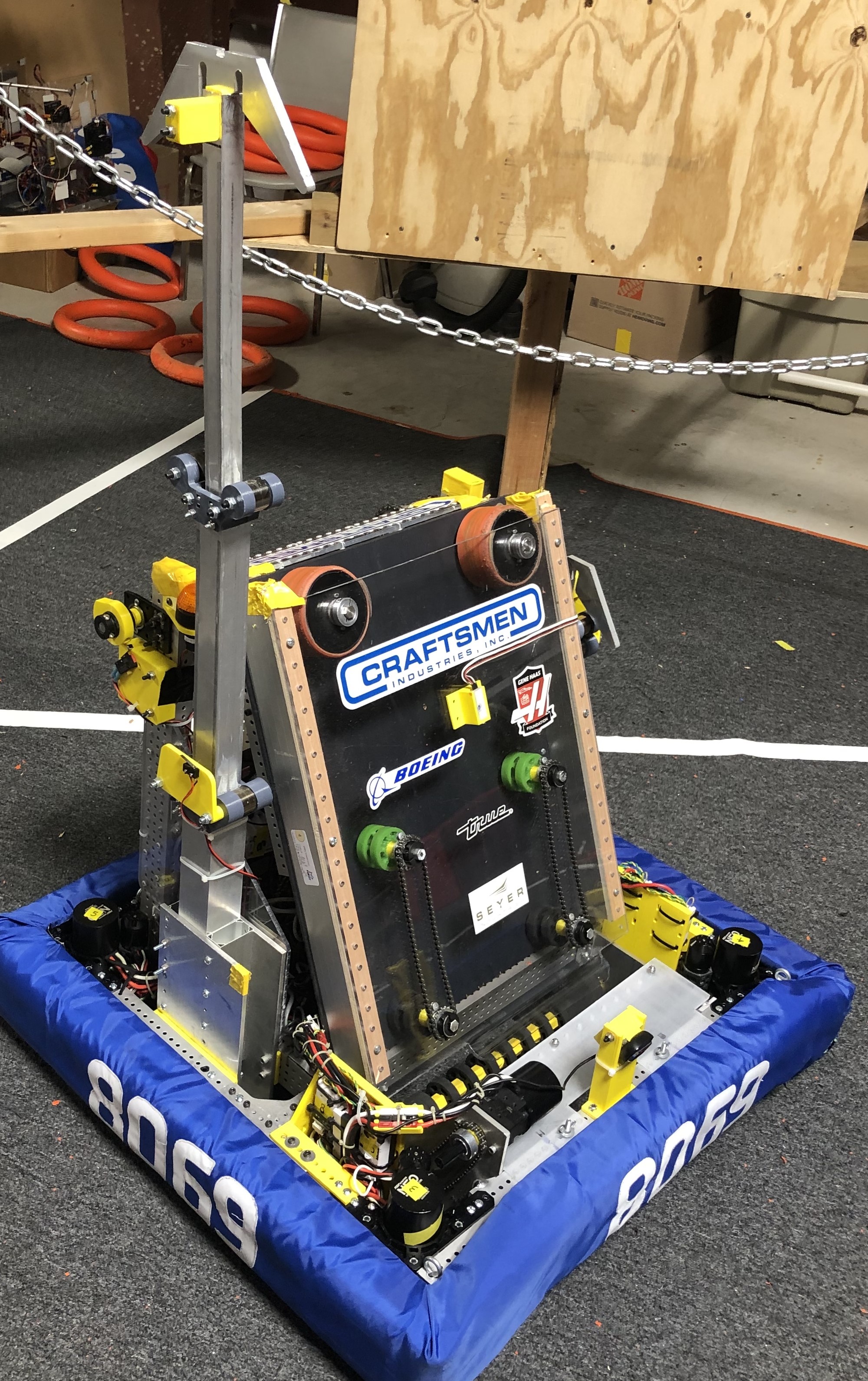
The climbers are a key component in this robot design, able to support and swiftly lift the robot onto the stage. The climber's extender itself is able to reach up to 47 inches, just under the height limit, allowing it to reach the chain with plenty of length to spare. The design stayed nearly the same throughout the design process, with it being completed fairly quickly for such a major component. During the prototyping process, we made the choice for the hooks to be 3D printed, but they ended up snapping off and breaking too easily, which was not ideal at the time, but, fortunately, we had new metal ones made. The hooks were designed so that we would be able to approach the Stage with either the front or the back of the robot and still be able to climb. These climbers were designed similar to the Climber in a Box from Andymark, but by using 3D printed pieces to hold the springs, we were able to keep the cost significantly lower.
Software/Electronics
Sensors
One of the sensors we used is to stop the note from going too far within the indexer. The sensor we used for the indexer is actually from a pinewood derby timer we built for a group called Love the Lou. The other sensors we used are for keeping the shooter from moving too far and breaking the robot. There is also a piece of metal behind the top sensor as a hard stop in case the sensor breaks. In the off-season we added another sensor below the one on the indexer to tell us when we have intaken a note.
Cameras
The two cameras we used on the robot are used for detecting notes and telling us where we are on the field. The first one was mostly used to help the driver line up with the notes. It was mounted above the intake in the center of the frame. The second camera was mounted on the other side of the robot. It was set up to detect targets that are placed around the field so that the robot can tell where it is. That information is combined with information from the sensors built into the swerve drive to let the robot track where it is on the field.
Code
This year, we switched to using command based java programming instead of timed based. For command based, we define commands, which are specific things that the subsystems do. We can also define sequences of commands. Then each button on the controller can be mapped to one or more commands. We found that this made it easier to break up the work between the different programmers. It also made it easier to make sure that we were not trying to do two things at once with one subsystem.
Auto
Because we switched to swerve drive this year, we wanted a new way to program auto. Previously, we mostly just used time and angle to program the driving. However, that approach makes it difficult to take full advantage of the swerve drive. So, we switched to using a program called PathPlanner, which let us map out paths we wanted the robot to follow. The program then created auto modes that would use the sensors built into the swerve drive to track its position so that it could follow those paths. It let us make more complex auto modes than we had been able to in the past.
