
2022 Rapid React
The Hungry Hungry Hornet
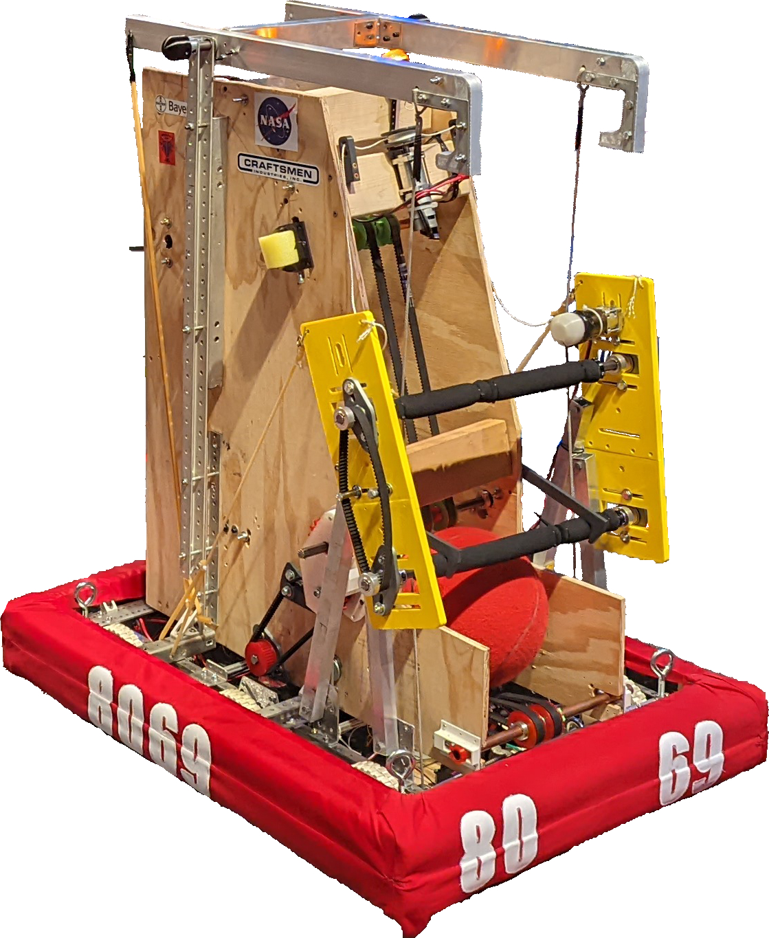
The Hungry Hungry Hornet was built in twelve weeks between January and March of 2022. Since we only had 5 students at the time, and none of us had ever built an FRC robot before, it was a learning experience for us all. We placed 15th out of 37 teams in the competition so it ended up working out great, even though there were many times that the robot broke during the matches.
Game Description
The 2022 challenge, RAPID REACT℠, consisted of a fifteen second autonomous (pre-programmed) period, followed by a two minute and fifteen second teleoperated (driver-controlled) period, including a 30 second endgame period. There were two objectives: scoring in the upper and lower hubs, which were large funnel-shaped rings, and climbing a series of rungs like monkey bars. During the autonomous period, robots tried to score points through taxiing, by leaving their designated starting position, and by scoring cargo, this year's game piece (a 9.5 inch ball), into the upper and/or lower hubs. In teleop, the drivers controlled their robots and continued to attempt to score cargo into the hubs. In endgame, robots went to the hangar to climb as high as possible for extra points.
Design Process
For the first week of the build season, we met virtually. We started with making drawings and CAD models of the different systems that we wanted. We also talked about strategy. By estimating how often we would be able to succeed in different tasks and how long those tasks would take to complete, we were able to come up with an idea of what we wanted the robot to do. Even after we switched to meeting in person, we continued to work on brainstorming; we were also able to start working on prototypes. After a few meetings, we narrowed down the designs. Throughout build season, as we found out what worked and what didn't, we modified our plans.
Intake
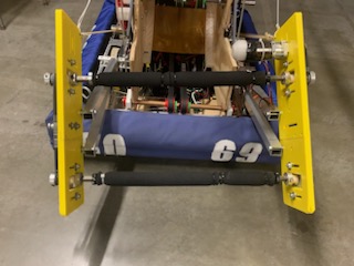
Loader
For the loader, we used a system of belts that compressed the cargo and brought it up to the shooter. There were belts above and below the cargo. We used gears to reverse the direction for one set of belts; in order to make the cargo go up instead of spinning, the belts on the top and the bottom had to be going in different directions.
Shooter
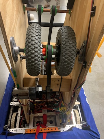
The shooter was made out of two pneumatic wheels, which spun and compressed the cargo against a bent piece of Lexan. It was able to shoot into the low hub. Two 775 pro motors were used to spin the wheels on a ½ inch hex shaft. The wheels were positioned a few inches apart in order to center the cargo against the Lexan. The Lexan was bent using curved 3D-printed pieces.
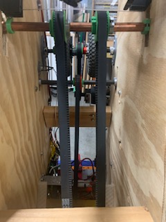
Hanger
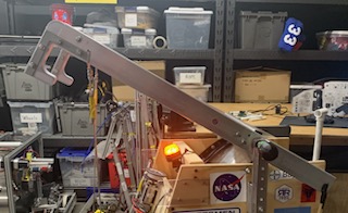
The hanger was the last major system on the robot that we designed. It reached the second rung. There were two parallel bars attached to the top of the robot on an axle that let them rotate. There was a bar between them to keep them together. We had a rope attached to one end of each bar that ran through a pulley attached to a motor at the bottom of the robot. On the same end there was a hook on each bar. We 3D printed the hooks and reinforced them with metal brackets. These were what held the robot when it was hanging. On the other end of each bar, we attached surgical tubing, which acted like a spring, pulling the end it was attached to down, which raised the end with the hooks. We would release the rope by unwinding the pulley, which would allow the surgical tubing to raise the hooks. Once they were over the rung we wanted to hang on, we would wind the rope back up, raising the robot.